Projects github.com/IC-Alchemy/VelocityEncoder
VelocityEncoder
Build a magnetic knob with fine control at slow speeds and wider sweeps when you turn faster. A practical Arduino guide for AS5600 and TMAG5273 sensors.
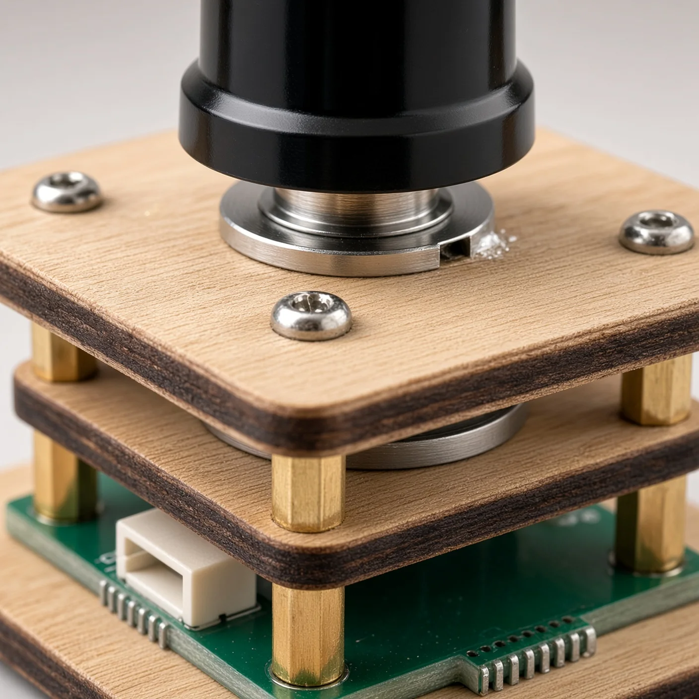
Overview
Turn slowly to make a small adjustment. Turn faster to move across more of a parameter’s range. VelocityEncoder reads a magnetic sensor over I2C, follows movement across multiple turns, and gives your sketch a change to apply to a value such as an effect amount, frequency, or menu setting.
There are three names to recognize: VelocityEncoder is the repository and project name; EncoderAlchemy is the name in the Arduino library metadata; MagEncoder is the C++ class you use, through #include <MagEncoder.h>.
The library supports the AS5600 and TMAG5273. This guide starts with an AS5600 and Serial Monitor, then shows the TMAG5273 changes. An OLED is optional.
- Get started
- Connect your sensor
- First sketch
- Tune the response
- Choose a sensor
- Troubleshooting
- Source and examples
Get started
You need an Arduino-compatible controller with a working Wire / TwoWire I2C implementation, a supported sensor board with its appropriate magnet, and connections for power, ground, SDA, and SCL. Select your controller’s board package in the Arduino IDE before uploading.
- Open the VelocityEncoder repository and choose Code → Download ZIP.
- In the Arduino IDE, choose Sketch → Include Library → Add .ZIP Library… and select that ZIP. Alternatively, place the library folder in your sketchbook’s
librariesdirectory. - Create a sketch and paste the first example below.
- Select your board and port, upload, and open Serial Monitor at 115200 baud.
The encoder core uses Arduino and Wire. The library metadata also declares Adafruit SH110X and Adafruit GFX Library as dependencies for the display helper and examples. Install those through Library Manager if you use an OLED; the serial-only sketch below does not include display headers. See the installation instructions.
Connect your sensor
Use the SDA and SCL pins for your controller’s selected I2C bus. Their physical pin numbers depend on the board and Arduino core. The table below describes signals, not the pin order of a particular connector.
| Sensor signal | Connect to |
|---|---|
| GND | Controller ground. |
| SDA | The controller’s I2C SDA signal. |
| SCL | The controller’s I2C SCL signal. |
| AS5600 VCC | A supply supported by your breakout. The library README lists 3.3 V or 5 V depending on the board; check its documentation. |
| TMAG5273 VCC | 3.3 V. The README lists the sensor’s supply range as 1.7–3.6 V. |
For a bare TMAG5273 connection, the repository wiring instructions also specify TEST to GND. Check whether your breakout already makes that connection. Its INT connection is optional for this polling example.
Check your breakout’s power and I2C logic requirements before connecting it. An AS5600 board’s ability to accept a 5 V supply does not establish that another sensor or controller can accept 5 V signals. Use your hardware’s documentation for connector orientation and magnet placement; this guide does not establish a physical Velocity Encoder connector pinout.
The library defaults are 0x36 for AS5600 and 0x35 for TMAG5273 through MagEncoder. A different TMAG5273 variant may use another address; choose its address explicitly.
First sketch
This AS5600 example keeps a floating-point parameter between 0.0 and 1.0. The sketch owns the value; the library supplies the movement to add to it.
#include <MagEncoder.h>

MagEncoder encoder;  // AS5600 at 0x36, using Wire
float parameter = 0.5f;

void setup()
{
    Serial.begin(115200);

    if (!encoder.begin())
    {
        Serial.println("Sensor not found. Check power, I2C pins, and address.");
        while (true)
            delay(10);
    }

    Serial.println("Turn the knob. Parameter starts at 0.5.");
}

void loop()
{
    encoder.update();

    const float change =
        encoder.takeParameterIncrement(0.0f, 1.0f, 4);

    if (change != 0.0f)
    {
        parameter = constrain(parameter + change, 0.0f, 1.0f);
        Serial.println(parameter, 6);
    }
}
begin() starts the I2C bus and returns whether initialization succeeded. update() refreshes the angle and derived state; it returns no value. Call it every loop: sensor reads are limited to one per 5 ms by default. Boards with a second bus can pass it explicitly, for example encoder.begin(Wire1) when that bus exists and is wired correctly.
Use takeParameterIncrement() in a normal fast loop. It consumes pending encoder counts, so each count is applied once. The separate getParameterIncrement() method describes the most recent sensor movement without consuming it; repeatedly adding that result can apply the same movement more than once.
The final argument, 4, sets the baseline number of turns used to calculate sensitivity. Velocity scaling changes the actual travel needed to span the range. The calculation is pending counts × range ÷ (counts per turn × baseline turns) × velocity scale. Keep the parameter as a float and clamp it in your sketch, as above.
These calls match the verified API and increment calculation. The sketch has been checked against that source; it has not been compiled or hardware-tested for this guide.
Tune the response
Start with the defaults and change one setting at a time. To customize the first sketch, replace MagEncoder encoder; with this configuration function and declaration. Keep the rest of the sketch in place.
MagEncoder::Config makeEncoderConfig()
{
    MagEncoder::Config cfg;
    cfg.readIntervalMs = 5;
    cfg.minVelDps = 90.0f;
    cfg.maxVelDps = 2400.0f;
    cfg.minScale = 0.008f;
    cfg.maxScale = 3.2f;
    cfg.curveExponent = 1.8f;
    cfg.velocitySmoothing = 0.08f;
    return cfg;
}

MagEncoder encoder(makeEncoderConfig());
Those values are the current defaults; sensor selection remains AS5600.
| Setting | What to adjust |
|---|---|
minScale | Raise it for larger changes during slow turns; lower it for finer adjustment. |
maxScale | Raise it for wider fast sweeps; lower it to restrain them. |
minVelDps | Speed in degrees per second below which the minimum scale applies. |
maxVelDps | Upper speed used to normalize the response curve. |
curveExponent | Shapes the middle part of the response curve. |
velocitySmoothing | Smaller values smooth changes in the velocity multiplier more. |
readIntervalMs | Minimum spacing between sensor reads. Keep calling update() frequently. |
maxRotations argument | More baseline turns reduce the change per count; fewer increase it. |
For fixed sensitivity without acceleration, set minScale and maxScale both to 1.0f. With equal scales, the turn-count argument sets the movement needed to span the range. Configuration is copied when you construct the encoder, so prepare it before constructing the object.
Choose a sensor
For a TMAG5273 at the library’s 0x35 default, replace the first sketch’s encoder declaration with:
MagEncoder encoder(MagEncoder::Sensor::TMAG5273);The same begin(), update(), and parameter-control loop applies. If you use the configuration function above, add these lines before return cfg; instead:
cfg.sensor = MagEncoder::Sensor::TMAG5273;
cfg.i2cAddress = 0x35; // Use the address of your actual sensor.| Sensor | Native angle counts | MagEncoder default address |
|---|---|---|
| AS5600 | 0–4095; 4096 per revolution | 0x36 |
| TMAG5273 | 0–5759; 5760 per revolution | 0x35 |
The driver defines TMAG5273 address constants ADDRESS_A = 0x35, ADDRESS_B = 0x22, ADDRESS_C = 0x78, and ADDRESS_D = 0x44. Match the fitted device rather than inferring its suffix from the product name. Some repository prose conflicts about the fitted part; the values here follow the address constants and MagEncoder’s address selection. The standalone TMAG5273 driver’s configuration has a different default (0x22), so set its address explicitly if you use it separately.
Useful readings for either sensor include getAngleDegrees(), getCumulativePosition(), getAngularSpeed() in degrees per second, and getCountsPerRevolution(). For a position mapping without acceleration, use mapPositionToRange(min, max, turns); resetCumulativePosition() establishes a new zero.
With TMAG5273 selected, encoder.tmag() also exposes cached X/Y/Z magnetic readings, temperature, and diagnostics after encoder.update(). See the explorer example for a fuller readout.
Troubleshooting
- Initialization fails: check supply, shared ground, the selected bus’s SDA/SCL pins, sensor selection, and address.
isConnected()reports initialization status; it does not continuously test for unplugged hardware. - The value runs away: use
takeParameterIncrement()once per loop. If usinggetParameterIncrement(), only apply it whengetCumulativePosition()changes. - Slow turns seem to do nothing: keep the controlled value floating-point and print enough decimal places. The default slow scale is deliberately small; increase
minScaleif needed. - A newly selected parameter jumps: call
clearPendingTicks()when changing which parameter or page the knob controls. - Fast motion loses counts or direction: remove long blocking work from the loop. The unwrapping calculation assumes less than half a revolution between angle samples.
- An OLED example will not compile: install Adafruit SH110X and Adafruit GFX Library. Include their headers before
AlchemyOled.h. The bundled knob example enables OLED by default. - No device appears on the bus: try the bundled
I2CBusCheckexample after adapting its pin settings to your controller. Its scan covers0x08–0x77, so it does not check the listed TMAG5273 C address0x78.
Source and examples
This guide follows source commit a8ed15d, checked on 1 November 2026. The library metadata reports version 1.1.0. No Git tags or published GitHub releases were present when checked; installation above uses repository source.
- VelocitySensitiveKnob: a parameter control with optional OLED output.
- TMAG5273Explorer: magnetic field, angle, temperature, and diagnostics on an OLED.
- I2CBusCheck: bus inspection at 100 kHz and 400 kHz.
- MagEncoder API and current repository.
The current source is under the MIT license, which allows use, modification, and redistribution with its copyright and license notice retained.